Plate Heat Exchangers were first produced in the 1920s and have since been widely used in a great number of sectors.
A plate exchanger consists of a series of parallel plates that are placed one above the other so as to allow the formation of a series of channels for fluids to flow between them.
The space between two adjacent plates forms the channel in which the fluid flows.
PLATE HEAT EXCHANGER WORKING PRINCIPLE
Heat Exchangers
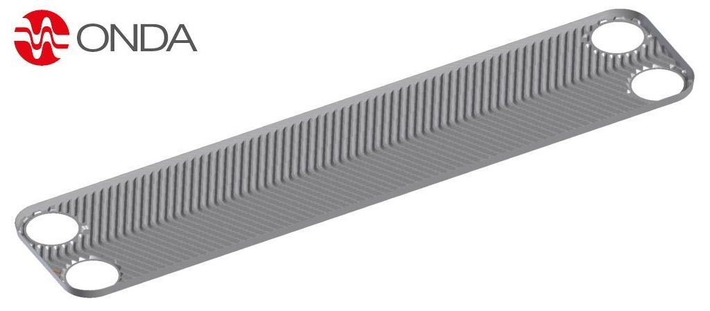
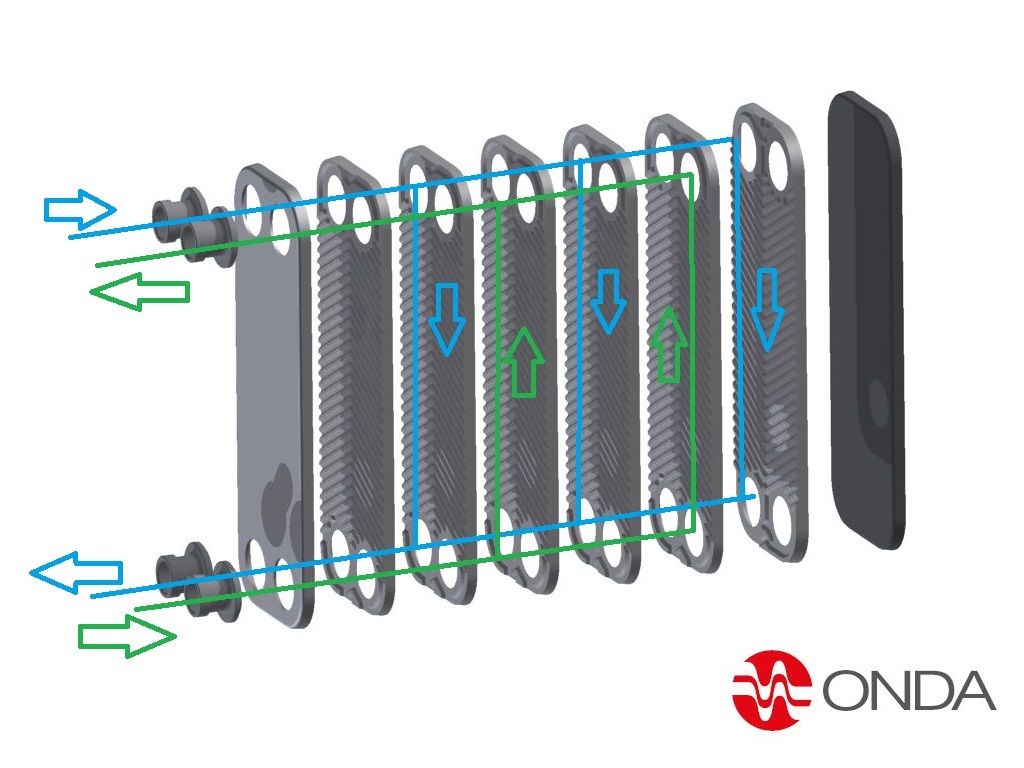
Plate Heat Exchangers were first produced in the 1920s and have since been widely used in a great number of sectors.
A plate exchanger consists of a series of parallel plates that are placed one above the other so as to allow the formation of a series of channels for fluids to flow between them.
The space between two adjacent plates forms the channel in which the fluid flows.
Inlet and outlet holes at the corners of the plates allow hot and cold fluids through alternating channels in the exchanger so that a plate is always in contact on one side with the hot fluid and the other with the cold.
The size of a plate can range from a few square centimeters (100 mm x 300 mm side) up to 2 or 3 square meters (1000 mm x 2500 mm side). The number of plates in a single exchanger ranges from just ten to several hundred, so reaching surface exchange areas up to thousands of square meters.
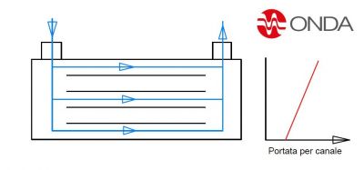
The figure shows the flow of fluids inside the exchanger. Fluids are divided into several parallel streams and can produce a perfect countercurrent.
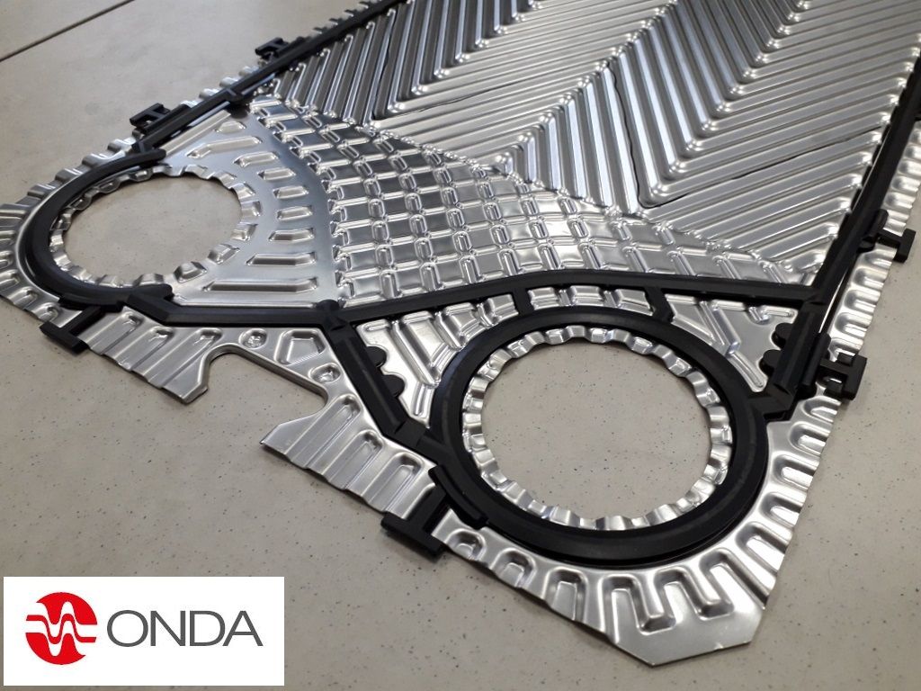
Generally, these plates are corrugated in order to increase the turbulence, the thermal exchange surface and to provide mechanical rigidity to the exchanger. Corrugation is achieved by cold forging of sheet metal with thicknesses of 0.3mm to 1 mm.
The most frequently used materials for the plates are stainless steel (AISI 304, 316), titanium and aluminium.
The corrugation on the plates forces the fluid on a tortuous path, setting a space between two adjacent plates b, from 1 to 5 millimeters.
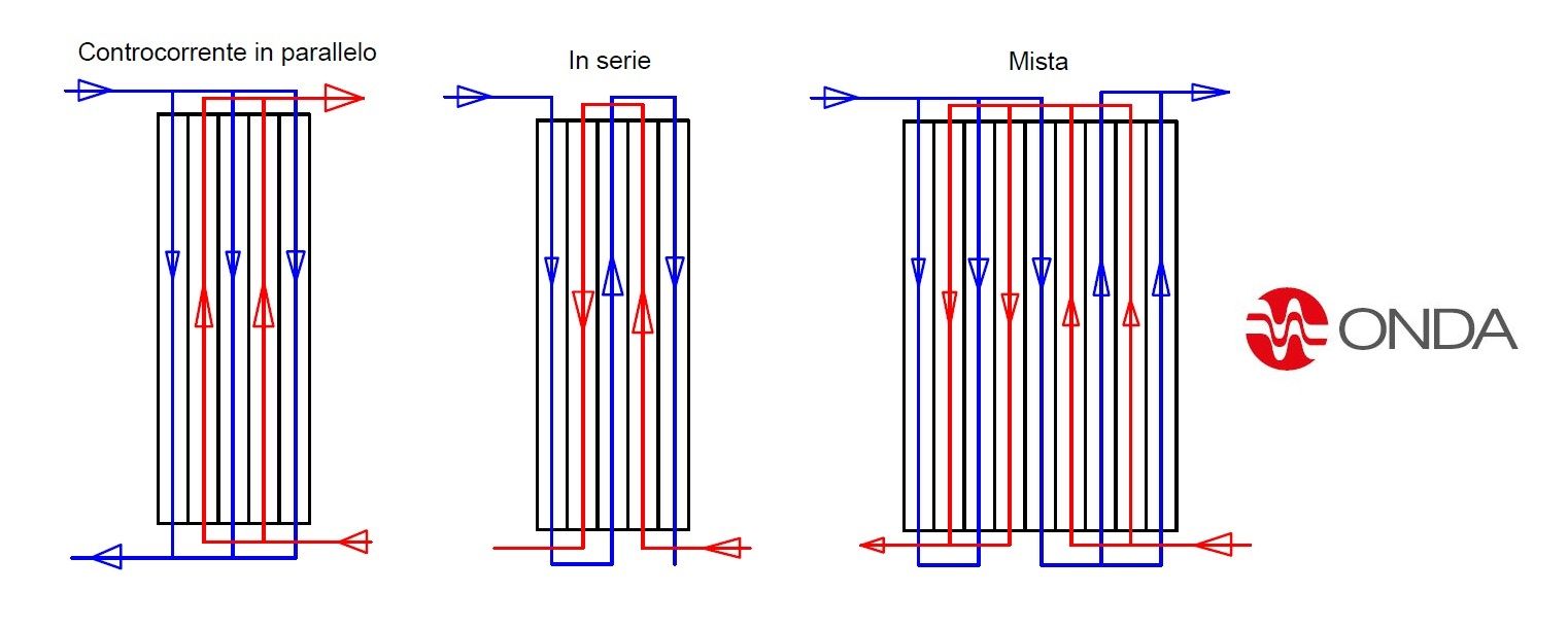
The fluids can cross the channels in series (a less common solution) or in parallel by making counter-current or current configurations.
The serial configuration is used when there is a small flow rate for each fluid but high heat jump; the greatest problem is with a high pressure drop and an imperfect counter-current.
The parallel configuration with countercurrent channels is used for high flow rates with moderate temperature drops, and is the most widely used.
When there is a great difference between the flow rates (or between the maximum permissible pressure drop) of the two fluids, the exchanger can run twice by the fluid with a lower flow (or higher losses) to balance the values of pressure drops or specific flow rates in the channels.
The figure shows the different configurations: in parallel, in series and mixed
One of the most common problems for plate heat exchangers is an irregular supply of the all channels in parallel. In fact, the fluid tends to distribute in greater quantities in the first channels rather than the last ones in order to balance the pressure drop.
As the number of plates increases, even distribution declines, resulting in a decrease in the overall performance of the exchanger.
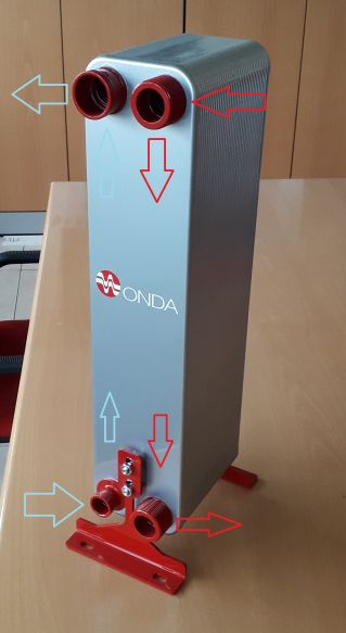
There are two basic types of plate heat exchangers: BPHE-Brazed Plate Heat Exchangers and PHE-Plate Heat Exchangers.
Plate and Frame Heat Exchangers
In the PHE the plates create a frame where the plates are pressed with headers and tie bars, and the seal is guaranteed by gaskets. Gaskets, in addition to their sealing effect, serve to direct the flow of the fluids, and are placed along the grooves at the edges of the plates.
The maximum temperatures used for sealing heat exchangers are between 80°C and 200°C while pressures can reach 25 bar.
Gaskets are available in various types of butyl or silicone rubber.
The main characteristics of these types of heat exchangers are:
– quick and easy dismantling for cleaning and control operations
– adaptation to variable operating conditions by adding or removing heat plates to modify the installed thermal flow
– any fluid leaks due to non-perfect sealing of the gaskets do not contaminate the other fluid but are directed away
– materials that are poorly adapted to soldering, such as titanium, may be used
– the gaskets limit the maximum pressure and temperature values
– potentially high costs due to the design of moulds, presses and all the production process
– high cost of the gaskets
Brazed Plate Heat Exchangers
Brazed plate heat exchangers have no headers, tie bars or sealing gaskets because the plates are furnace brazed at temperatures of 1100°C.
During the assembly phase, a sheet of brazing material (generally copper but also nickel) is placed between the plates, the pack is pressed and subsequently baked for some hours.
The BPHE exchanger is more compact, lighter and less bulky than one with gaskets.
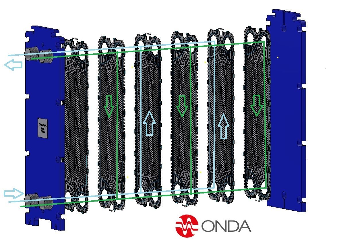
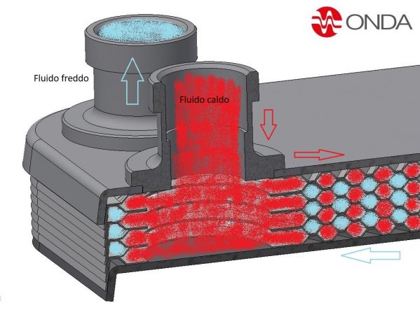
The image shows the path made by the hot and cold fluid.
The brazing material carries out the function both of the gaskets and the frame.
These exchangers are generally used with chevron corrugated plates, which are assembled alternating the corrugation directions in order to create a lattice contact.
The crossing points between the corrugations of two coupled plates form a dense network of contact points that confer pressure tightness and induce swirling streams that improve heat exchange.
In this way, the turbulence of the fluids is high even at low nominal input speeds and the flow passes from laminar to turbulent for low flow rates.
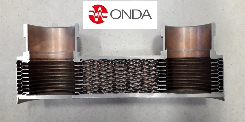
The figure shows a cross section of an exchanger with 8 plates in total (6 of which are useful for heat exchange) in which the 3 channels used for the passage of the refrigerant fluid (in light blue) and the 4 for water (in red) are seen.
It is immediately noticeable that the path made by the fluids is chaotic, in fact, the cross section varies continuously.
The main disadvantage of these exchangers is that they are not removable and so maintenance and cleaning are not possible or at least difficult, and no flexibility exists as the number of plates can in no way be varied.
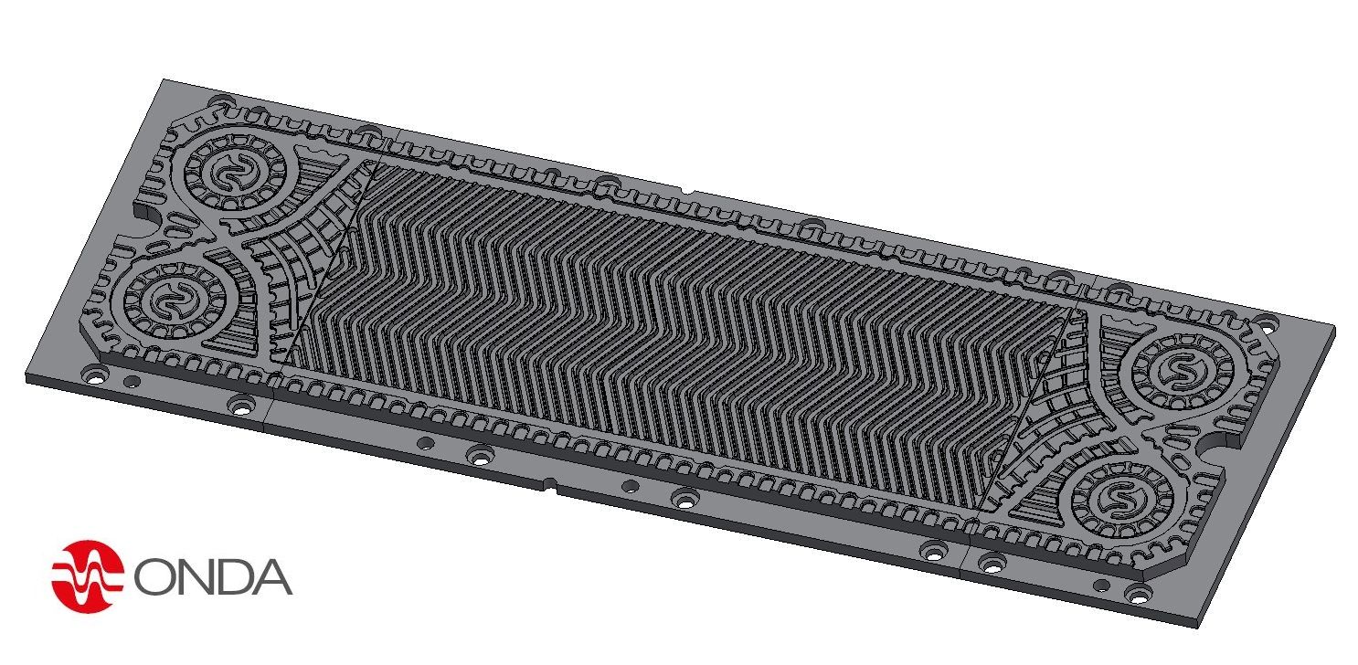
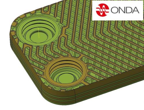
The surface of the plates is corrugated in order to increase the turbulence of the fluid during the flow into the channels.
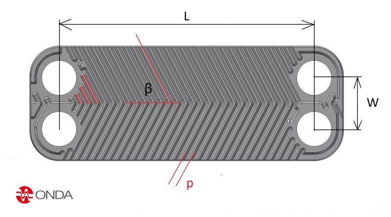
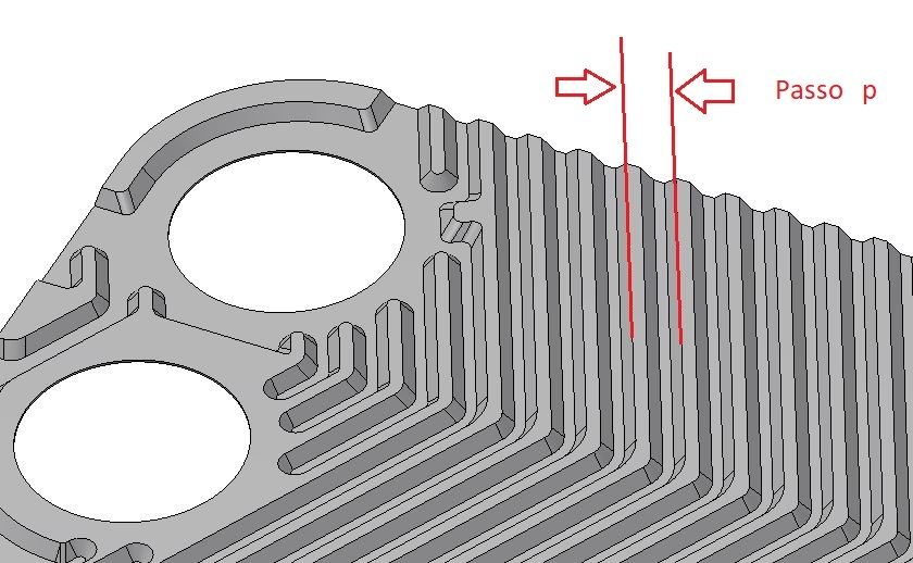
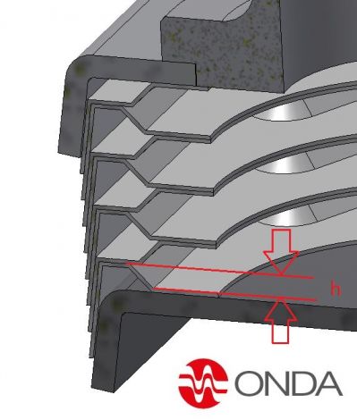
The figure highlights the main geometrical parameters of the corrugation:
Corrugation pitch p; corrugation height b and chevron angle β compared to the main direction of the flow.
The inclination of the plate corrugations has a determining effect on thermal exchange and load losses. In fact, a pair of plates with a high β angle (> 45 °) gives a turbulence and therefore a high heat exchange with a higher pressure drop.
A smaller angle (β <45 °) causes a lower turbulence flow and lower heat exchange coefficients but also lower pressure drops.
The search for a compromising β angle between high exchange coefficients and acceptable load losses is therefore essential.
The corrugation height b has an important effect on the exchange coefficients because a greater depth causes greater turbulence.
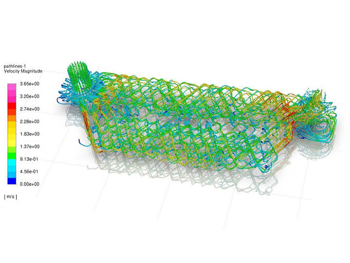
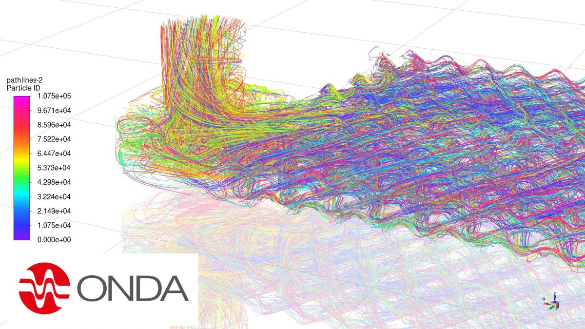
These two picture below show an Wieland Onda case study of the flow inside the channel of a braze plate heat exchanger, you can see the flow going inside the channel in and out of the BPHE
The height and pitch of the corrugations increase the plate exchange surface area: the surface enlargement factor φ is defined as:
Φ = actual corrugated surface area / projection area corrugated surface
The actual area is difficult to compute, so in order to compare different exchangers, reference is made to the projected area.
It should be kept in mind that heat exchangers with the same projected area (ie plates of the same size) may have different effective areas depending on the value of the surface enlargement factor φ.
The ratio between the plate length L and the plate width W also affects performance but to a lesser degree than other variables. In general, a high ratio between plate length and width gives high exchange rates but higher load losses.
Enrico Golin, R&D Wieland Onda Srl